The design need not be overly realistic but more of an abstract representation with simple colors. Your own drawing or mock-up does not have to be the same. In my case, to get inspiration, I drew a real light bulb. However, one does not have to draw or retrace all the parts of a light bulb to know that is what it is. Generally, just the glass bulb, the filament, the base cap, and maybe some indication that it is glowing are all that are needed. However, if this were an infographic about the parts of a light bulb, then a more detailed sketch might be required.
In this example, let’s look at some of the simple shapes I drew. To create parts of the bulb, I used the Ellipse tool holding the Shift key down and the Rectangle tool and modified the points on the rectangle using the Direct Selection tool. I can also use the arrow keys on my keyboard to nudge individual points left and right. Refer to Figure 8-31.
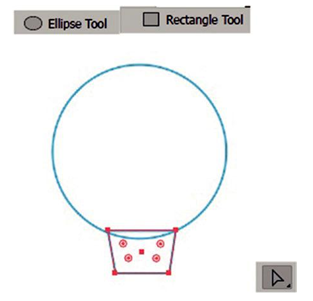
Figure 8-31. Use the Ellipse, Rectangle, and Direct Selection tools to modify various shapes of a bulb
I also used the Rounded Rectangle tool to create three screw elements on a rectangle, above the base contact cap which is a rectangle. I could then use either the Pen tool or the Rectangle tool again to create the cap’s electrical foot contact. Refer to Figure 8-32.
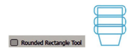
Figure 8-32. Create other parts of the bulb using the Rounded Rectangle tool
The stem/glass support was drawn with the Rectangle tool, and parts of the filament were drawn with the Ellipse tool, Line Segment tool, and Pen tool for wires. Some of these lines were drawn on “drawing layer 2” while I hid and locked the “drawing layer 1.” Refer to Figure 8-33.
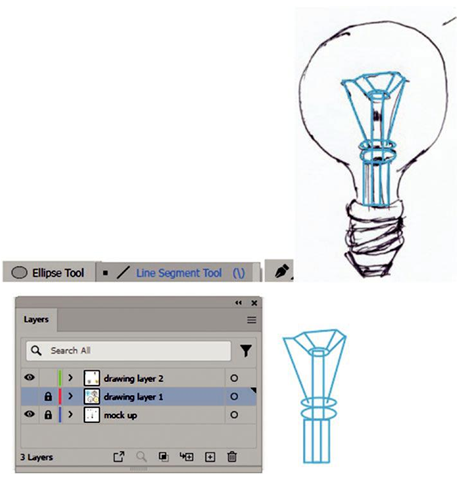
Figure 8-33. Drawing parts of the filament using the Ellipse, Line, and Pen tools while locking and hiding other some layers in the Layers panel to get a more accurate trace
The light source was drawn with the Star tool on drawing layer 1 and set to Radius 1:
1.1528 in and Radius 2: 0.5278 in and 20 points. Refer to Figure 8-34.
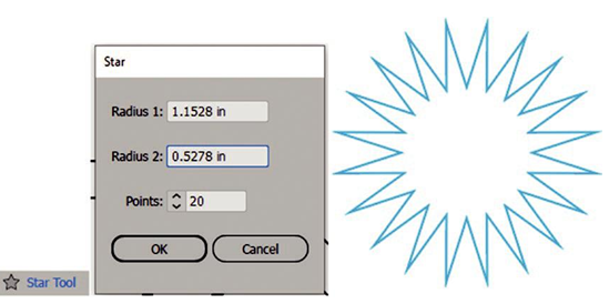
Figure 8-34. Using the Star tool and Star dialog box to create light rays
I also used the Polygon tool while holding down the Shift key to create two eight- sided octagons. The outer is about 4.3291 inches for width and height, and the inner is about 3.6763 inches for width and height. First is the outer shape then the inner.
Remember to use your Shape options in the Control panel if your polygon is not eight sided. You can scale using the Selection tool and then arrange these behind the other shapes if they are not in the correct order. Try using various the Object ➤ Arrange settings as required. Refer to Figure 8-35.
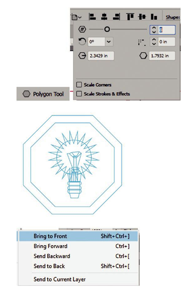
Figure 8-35. Using the Polygon tool and the Control panel to create and edit the octagons and using the Object>Arrange menu to move some layers behind others